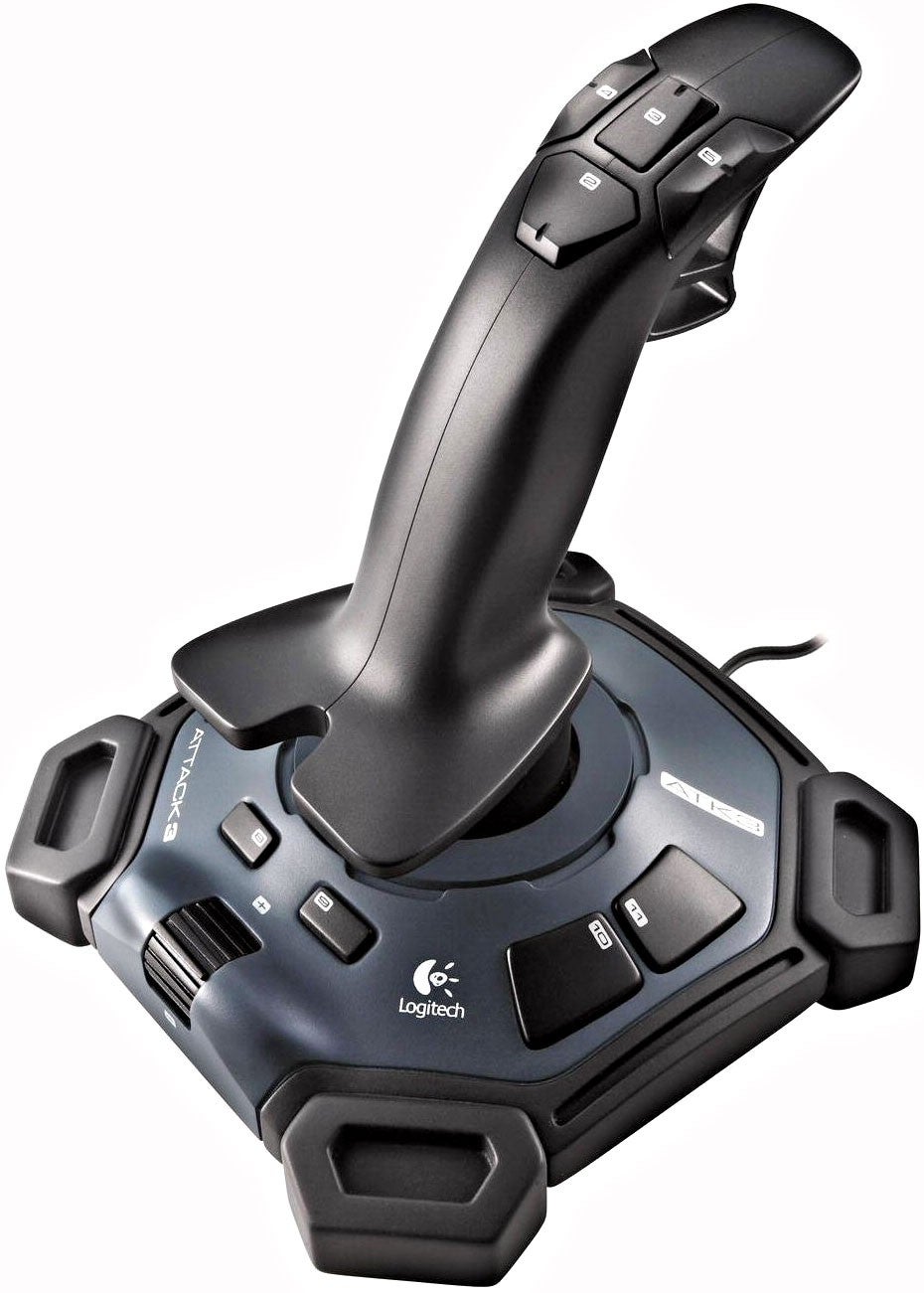
DC Motor Speed Control And Direction Using Joystick Circuit Diagram In many of the applications it is required to alter the direction of DC motor instantly. Like in washing machine, mixer, drilling machine winding - rewinding machine etc. Changing the direction of DC motor using joystick is most suitable and handy method.In industries the joystick control is most preferable way to control machinery that is operated with DC motor. The best example is 3 axis
Additionally, the further away from the center the joystick is pushed (in either direction), the faster the motor speed will be in that same direction. So, users can control the DC motor speed in this way. The joystick control method for DC motors is currently used in several different applications, including as: 1.
Arduino Joystick 2 Dc Motor Control Circuit Diagram
up/down controller, TV up/down controller are few application examples. The board provides superb performance, smooth movement of motor, and hassle-free use. You only need to connect the motor wires, power the board, and you ready to go.The controller has 3 main elements, Atmega328 Micro-Controller, LMD18201 DC Motor H-bridge, and Joystick Arduino Joystick 2 Dc Motor Control : Arduino Joystick 2 dc motor control Youtube Video Documents Inside, there is a pretty simple set-up: a small DC motor, a potentiometer (a variable resistor), and a control circuit. The motor is attached by gears to the control wheel. As the motor rotates, the potentiometer's resistance changes, so the control circuit can precisely regulate how much movement there is and in which direction.
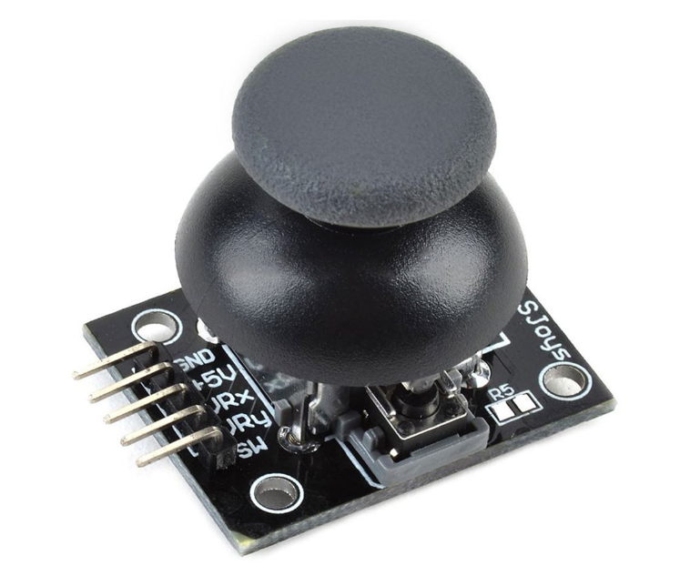
This post shows how to control a DC motor speed and direction of rotation using Arduino uno, joystick and L293D motor driver. The joystick (PS2 Joystick) consists of two potentiometers (one for the X-axis and the other for the Y-axis) and a push-button. With one potentiometer we can control the speed and rotation direction of a DC motor.

How to control a DC Motor with Joystick & Arduino Circuit Diagram
This code allows you to control the speed and direction of a DC motor using the Y-axis of a joystick. The motor will stop when the joystick is in the central position, rotate forward when the joystick is pushed upward, and rotate backward when the joystick is pulled downward, with the speed proportional to the joystick's position. How Analog joysticks Work. A typical analog joystick module consists of two potentiometers and a pushbutton: X-Axis Potentiometer: Detects left and right movement.; Y-Axis Potentiometer: Detects up and down movement.; Pushbutton: Activated when the joystick is pressed down.; When you move the joystick in any direction, the position changes the resistance of the two potentiometers.
