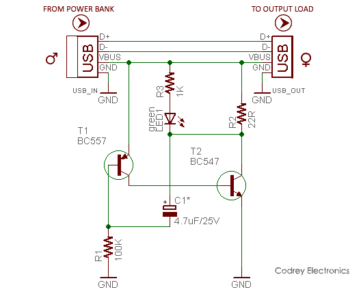
How to make a Power Bank at Home Circuit Diagram Here is simple circuit to keep your USB Power Bank active "awake" so it stops automatically shutting off. Click the SHOW MORE tab below for links. *Building
Power Bank circuit using a single USB output port compact module: In this circuit we will use a compact module, it comes with a USB 5volt 1A rating. It is used where only one USB output is sufficient for use, also saves space as it is very compact. The major advantage for this module is that it restricts simultaneous charging and discharging of
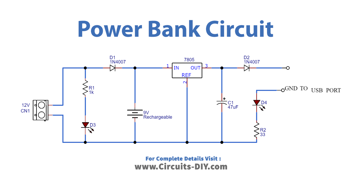
Homemade 10000mah Power Bank Circuit Diagram
The following components are required to make Power Bank Circuit. First place and solder the female USB port and 12DC input pin on the Vero board. Now, connect a resistance of 1K in a way that one end is connected to a 12V pin and one end to the positive pin of the LED. Connect the negative of an LED to a 12V negative pin.

The power is stored in a power ban by charging and it can be used when you need, In any power bank, A battery or combination of some small special batteries (cells) used to produce the power source to provide for mobile or other electronic gadgets battery charging. The USB port is used to input for charging and also for output. It has a circuit

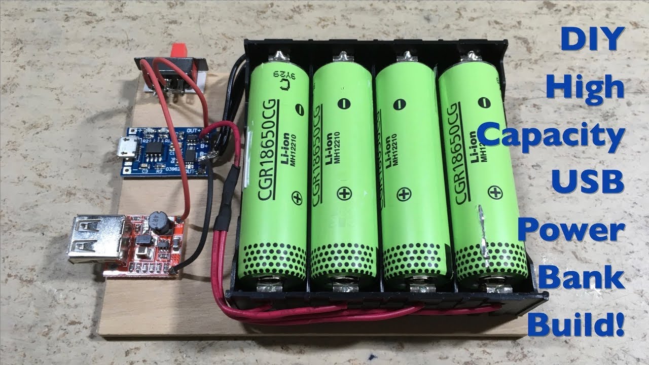
DIY Power Bank ? : 8 Steps (with Pictures) Circuit Diagram
Charging the Power Bank Circuit: Red color LED indicates the battery charging in this power bank circuit, Blue color LED indicates the charge complete, Charging the Mobile Phone with this Power Bank: 1. Connect the USB to micro B cable to the output of boost converter. 2. Turn the slide switch ON. 3.

In this small project I will show you how to create a DIY USB Type-C PD powerbank the super simple way. To do that I will firstly test a powerbank PCB based around the IP5328P IC I got from Aliexpress. The measurements will show us how suitable the PCB is for creating a DIY powerbank.