SOLVED For the following feedback amplifier draw the A Circuit Diagram Current feedback amplifiers are used in broadcast video systems, radar systems, IF and RF stages, RGB distribution systems and many other high speed circuits. As with any new circuit, there are several new rules that must be kept in mind to prevent problems. Because current feedback amplifiers act very much the same as regular op amps, it is
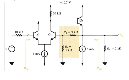
Figure 4. Internal circuitry of an op-amp [2] 1.2. Kirchhoff's Current Law applied to Op-amps An operational amplifier circuit can be analyzed with the use of a well-accepted observation known as Kirchhoff's Current Law (KCL). KCL simply states that the currents entering a node are equal in magnitude to the currents leaving that same node. A

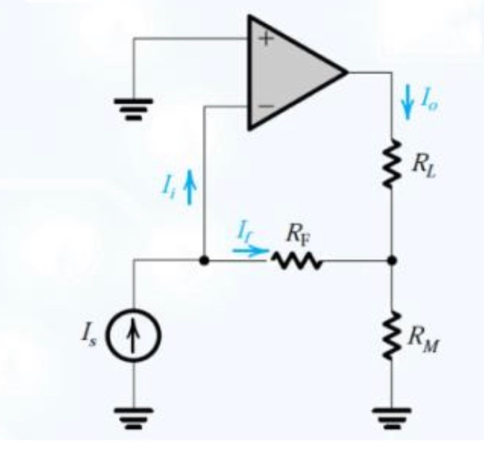
PDF MT Circuit Diagram
These two circuits illustrate the basic distinctions between current-feedback and voltage-feedback amplifiers. In both cases, the feedback network is connected to an (inverting) input node. In Figure 1, the emitter presents a low imped-ance input, while in Figure 3 the base presents a high impedance input.

Operational Amplifier Circuits Review: Ideal Op-amp in an open loop configuration Ro Ri + _ Vp Vn Vi + _ AVi + Vo Ip In An ideal op-amp is characterized with infinite open-loop gain A→∞ The other relevant conditions for an ideal op-amp are: 1. Ip =In =0 2. Ri =∞ 3. Ro =0 Ideal op-amp in a negative feedback configuration When an op-amp
Design Note 46: Current Feedback Amplifier "Do's and Don'ts" Circuit Diagram
Current feedback op amps do not have a fixed gain-bandwidth product. Figure 4: Current Feedback Amplifier Frequency Response . Gain is manipulated in a CFB op amp application by choosing the correct feedback resistor for the device (R2), and then selecting the bottom resistor (R1) to yield the desired closed loop gain.